In short
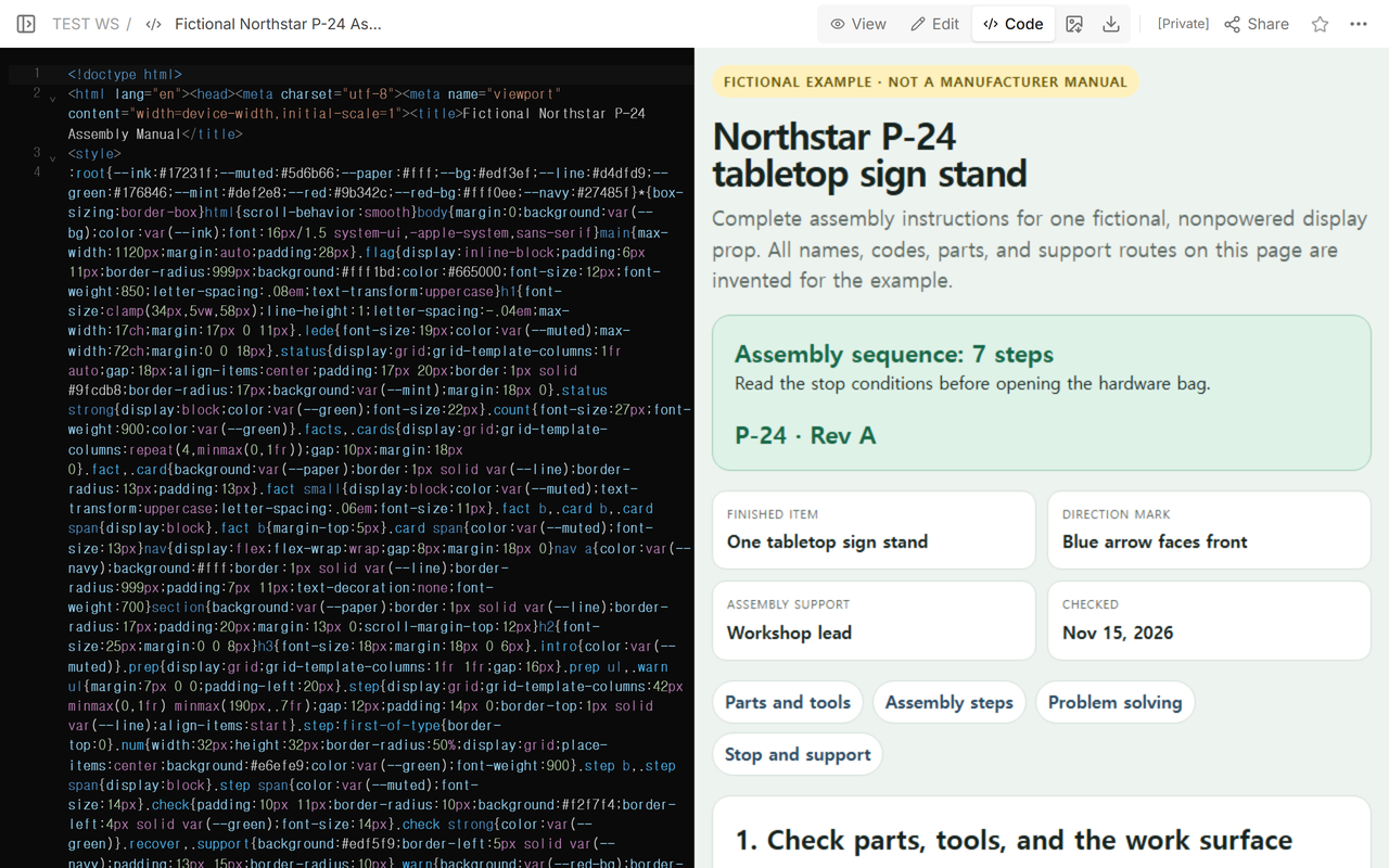
This guide assembles one fictional Northstar P-24 tabletop sign stand from start to finish.
Inventory the eight part groups and three required tools before opening the hardware bags.
Follow the seven actions in order and use the “Complete when” check after every action.
Stop rather than forcing a mismatched, cracked, bent, sharp, or damaged part.
The Northstar P-24 is a fictional, nonpowered display prop created for this guide. Its name, parts, fasteners, markings, hazards, and support route are invented. It is not a real product, and these instructions must not be applied to a lamp, shelf, seat, step, or load-bearing item.
The worked manual is the main deliverable, not a blank outline. You can read it below, open the same example in the NOS screens, or download the complete fictional assembly manual as an HTML file.
What must be ready before assembly?
Clear a stable, level table. Put a soft cloth under the base and a small tray beside it for fasteners. Keep the sign panel flat until its numbered step. The required assembly tool is the supplied hex key marked TOOL-A; the cloth and tray are also required because they protect the parts and keep the hardware accounted for.
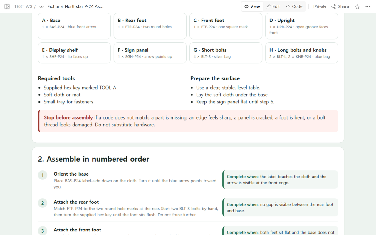
Lay out all eight part groups before beginning:
- A · BAS-P24 base: one, with a blue arrow that defines the front.
- B · FTR-P24 rear foot: one, identified by two round-hole marks.
- C · FTF-P24 front foot: one, identified by a square mark.
- D · UPR-P24 upright: one, with an open groove that must face front.
- E · SHF-P24 display shelf: one, with a lip that must face up.
- F · SGN-P24 sign panel: one, with an arrow that must point up.
- G · BLT-S short bolts: four in the fictional silver bag, used only for the feet.
- H · BLT-L long bolts and KNB-P24 knobs: two of each in the fictional blue bag, used for the upright and shelf.
Stop before step 1 if a code does not match, a part is missing, an edge feels sharp, a panel is cracked, a foot is bent, or a bolt thread looks damaged. Do not substitute hardware.
How do you assemble the Northstar P-24?
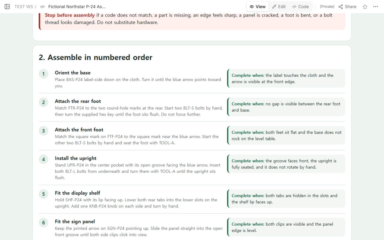
- Orient the base. Put BAS-P24 label-side down on the cloth. Turn it until the blue arrow points toward you. Complete when: the label touches the cloth and the arrow is visible at the front edge.
- Attach the rear foot. Match FTR-P24 to the two round-hole marks at the rear. Start two BLT-S bolts by hand, then turn TOOL-A until the foot sits flush. Do not force it farther. Complete when: no gap is visible between the foot and base.
- Attach the front foot. Match the square mark on FTF-P24 to the square mark near the blue arrow. Start the other two BLT-S bolts by hand and seat the foot with TOOL-A. Complete when: both feet sit flat and the base does not rock on the level table.
- Install the upright. Stand UPR-P24 in the center pocket with its open groove facing the blue arrow. Insert both BLT-L bolts from underneath and turn them with TOOL-A until the upright sits flush. Complete when: the groove faces front and the upright does not rotate by hand.
- Fit the display shelf. Hold SHF-P24 with its lip facing up. Lower both rear tabs into the lower upright slots. Add one KNB-P24 knob on each side and turn the knobs by hand. Complete when: both tabs disappear into the slots and the lip faces up.
- Fit the sign panel. Keep the printed arrow on SGN-P24 pointing up. Slide the panel straight into the open front groove until both side clips become visible. Complete when: both clips are visible and the top edge is level.
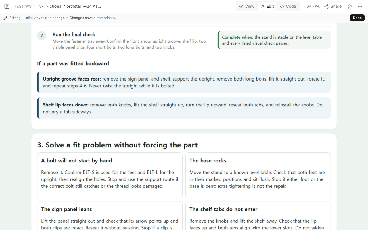
- Run the final check. Move the fastener tray away. Confirm the front arrow, forward-facing groove, upward shelf lip, two panel clips, four short bolts, two long bolts, and two knobs. Complete when: every visual check passes and the stand does not rock on the level table.
Each action ends with a visible result. This follows the U.S. Consumer Product Safety Commission guidance that instructions describe the actions or procedures needed to perform a task. The parts-and-tools inventory and numbered order also apply IKEA’s official advice to check the listed parts, spares, and tools before starting and to follow the assembly steps in order.
Official basis: CPSC’s Manufacturer’s Guide to Developing Consumer Product Instructions and IKEA’s assembly guidance. These sources shape the manual’s structure; they do not validate the invented P-24 product.
What if a part was installed backward?
If the upright groove faces rear, remove the sign panel and shelf first. Support the upright, remove both long bolts, lift it straight out, rotate it, and repeat steps 4-6. Never twist the upright while it is bolted to the base.
If the shelf lip faces down, remove both knobs, lift the shelf straight up, turn the lip upward, reseat both tabs, and reinstall the knobs. Do not pry a tab sideways. These recovery paths return to the last known correct orientation instead of adding force to the wrong fit.
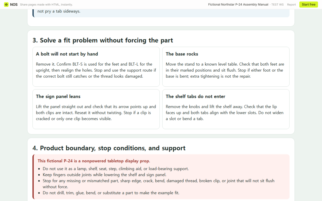
How do you solve common fit problems?
A bolt will not start by hand
Remove it. Confirm that BLT-S is being used for a foot and BLT-L for the upright, then realign the holes. If the correct bolt still catches or its thread looks damaged, stop and use the support route.
The base rocks
Move the stand to a known level table. Check that both feet are in their marked positions and sit flush. Stop if the base or either foot is bent. Extra tightening is not the repair for a bent part.
The sign panel leans
Lift it straight out. Confirm that its arrow points up and both clips are intact, then reseat it without twisting. Stop if a clip is cracked or only one clip becomes visible.
The shelf tabs do not enter
Remove the knobs and lift the shelf away. Confirm that the lip faces up and both tabs align with the lower slots. Do not widen a slot or bend a tab.
When must assembly stop?
- Stop for a missing or mismatched part, sharp edge, crack, bend, damaged thread, broken clip, or joint that will not sit flush without force.
- Keep fingers outside the joints while lowering the shelf and panel.
- Do not drill, trim, glue, bend, or substitute a part to make the example fit.
- Do not use the fictional P-24 as a lamp, shelf, seat, step, climbing aid, or load-bearing support.
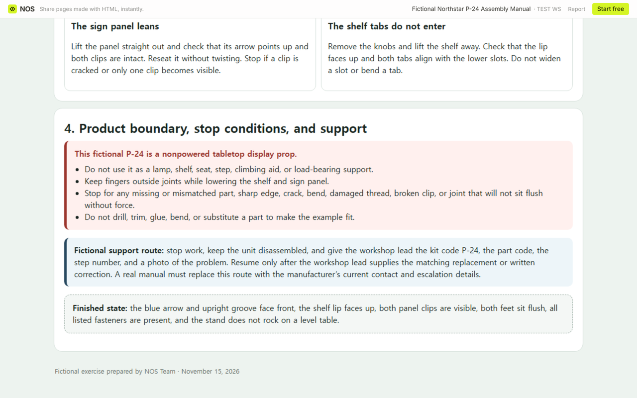
The support route is equally specific: leave the unit disassembled and give the fictional workshop lead the kit code P-24, the affected part code, the step number, and a photo of the problem. Resume only after the workshop lead supplies the matching replacement or a written correction. A real manual must replace that invented route with the manufacturer’s current contact and escalation details.
Finished state: the blue arrow and upright groove face front, the shelf lip faces up, both panel clips are visible, both feet sit flush, every listed fastener is present, and the stand does not rock on a level table.
How can the manual be shared without the editor?
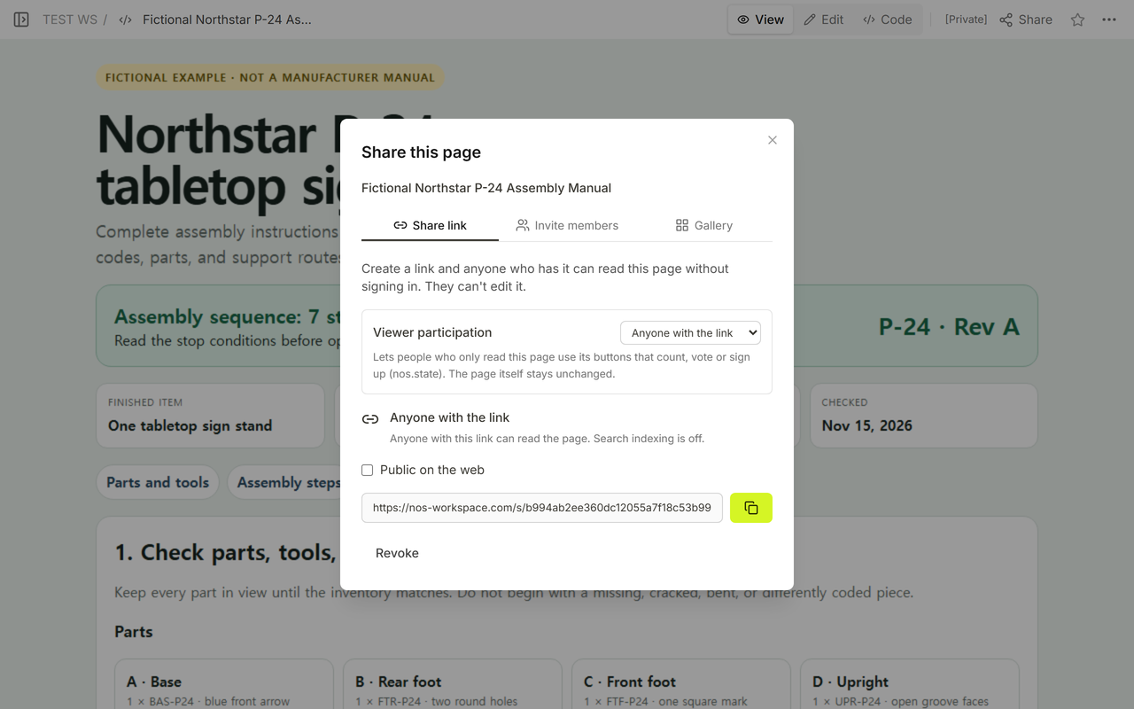
In the captured NOS Share panel, anyone with the reader link can view this example without signing in, while editing remains unavailable from that reader address. Send the reader link to assemblers and keep the workspace address with the people responsible for maintaining the manual.
When not to do this
- Do not use this fictional example for a real product or infer unlisted torque, load, temperature, material, certification, or regulatory limits from it.
- Do not replace a manufacturer-approved manual, required warning, engineering drawing, or regulated instruction with this page.
- Do not publish restricted drawings, access codes, customer information, or private production records at a reader link.
- Do not treat a checked date as proof that the instructions still match a changed product revision.
Using NOS for an assembly manual
NOS Workspace displays the fictional HTML in Code, View, and Edit and provides a separate reader address through Share. The example keeps the parts, tools, actions, recovery paths, problems, safety boundary, and support route on one scrollable page. Check the current pricing page if plan details matter; this guide does not copy a price.
Related product documentation
Use the product specification guide to record decisions before a product is built. Use the care card template for care after assembly. For routes, limits, and contacts during an event setup, see the online exhibitor manual.